Product Description
Product introduction
| Modulo | Above 0.8 |
| Numero di Denti | Above 9teeth |
| Angolo d’Elica Helix Angle | Up to 45 |
| bore diameter | Above 6mm |
| axial length | Above 9mm |
| Gear model | Customized gear accoding to customers sample or drawing |
| Processing machine | CNC machine |
| Material | 20CrMnTi/ 20CrMnMo/ 42CrMo/ 45#steel/ 40Cr/ 20CrNi2MoA/304 stainless steel |
| Heat treattment | Carburizing and quenching/ Tempering/ Nitriding/ Carbonitriding/ Induction hardening |
| Hardness | 35-64HRC |
| Qaulity standerd | GB/ DIN/ JIS/ AGMA |
| Accuracy class | 5-8 class |
| Shipping | Sea shipping/ Air shipping/ Express |
My advantages:
1. High quality materials, professional production, high-precision equipment. Customized design and processing;
2. Strong and durable, strong strength, large torque and good comprehensive mechanical properties;
3. High rotation efficiency, stable and smooth transmission, long service life, noise reduction and shock absorption;
4. Focus on gear processing for 20 years.
5. Carburizing and quenching of tooth surface, strong wear resistance, reliable operation and high bearing capacity;
6. The tooth surface can be ground, and the precision is higher after grinding.
| Hardness: | Hardened Tooth Surface |
|---|---|
| Gear Position: | External Gear |
| Manufacturing Method: | Cut Gear |
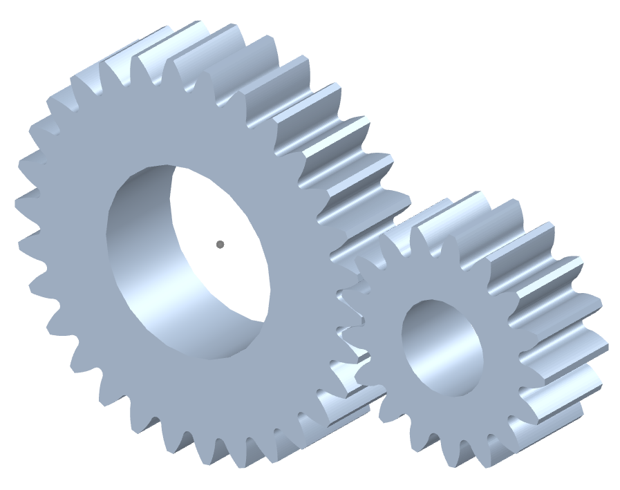
| Toothed Portion Shape: | Spur Gear |
| Material: | Cast Steel |
| Type: | Worm And Wormwheel |
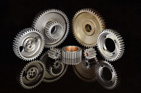
| Samples: |
US$ 10/Piece
1 Piece(Min.Order) | |
|---|
| Customization: |
Available
| Customized Request |
|---|
How do you ensure proper alignment when connecting spur gears?
Proper alignment is crucial when connecting spur gears to ensure smooth and efficient gear operation. Here’s a detailed explanation of how to ensure proper alignment when connecting spur gears:
- Visual Inspection: Start by visually inspecting the gears, gear shafts, and associated components for any visible misalignment or damage. Look for signs of wear, uneven tooth engagement, or any abnormalities that may affect alignment.
- Shaft Alignment: Align the gear shafts accurately before connecting the gears. Proper shaft alignment ensures that the gears are positioned correctly relative to each other. This can be achieved through various alignment techniques, such as using alignment tools, laser alignment systems, or measuring devices. The goal is to ensure parallel or coaxial alignment between the gear shafts.
- Backlash Adjustment: Adjust the backlash between the gear teeth to achieve proper alignment. Backlash refers to the slight gap between the mating teeth of gears. It is important to maintain an appropriate amount of backlash to allow for smooth gear engagement and minimize the risk of binding or jamming. Follow the manufacturer’s recommendations or industry standards for the recommended backlash range and adjust as necessary during gear installation.
- Check Gear Mesh: Verify the gear meshing pattern to ensure proper alignment. The gear teeth should mesh smoothly and evenly without any signs of excessive or uneven contact. If there are indications of improper meshing, such as concentrated contact on a specific area of the tooth, it may imply misalignment or other issues that need to be addressed.
- Shim Adjustment: If misalignment is detected, shimming can be employed to correct it. Shimming involves placing thin metal shims between the gear and the shaft to adjust the positioning and alignment. Shims are available in various thicknesses, allowing for precise alignment adjustments. Careful measurement and selection of the appropriate shim thickness can help achieve the desired alignment.
- Tightening Bolts: When connecting the gears to the shafts, ensure that the bolts or fasteners are tightened evenly and to the recommended torque specifications. Uneven tightening can introduce misalignment or uneven load distribution, leading to gear misalignment and potential issues.
- Post-Installation Verification: After connecting the gears, perform a final verification of the alignment. Rotate the gears manually or through the gear system’s intended operation and observe the gear meshing behavior. Look for any signs of abnormal noise, vibration, or irregular tooth engagement. If any issues are detected, further adjustments or inspections may be necessary.
- Regular Maintenance: Implement a proactive maintenance program that includes periodic inspections and alignment verification. Gears can experience wear or misalignment over time due to factors such as load variations, temperature changes, or prolonged operation. Regular maintenance allows for early detection and correction of alignment issues, ensuring optimal gear performance and longevity.
Proper alignment is essential for maximizing the efficiency, durability, and reliability of spur gear systems. By following these alignment practices and considering the manufacturer’s recommendations, industry standards, and expert advice, you can ensure proper alignment when connecting spur gears.
It’s important to note that the specific alignment techniques and procedures may vary depending on the gear system’s design, size, application, and other factors. Consulting with gear manufacturers, engineers, or alignment specialists can provide further guidance on the recommended alignment practices for your specific gear system.
Can you provide examples of machinery that use spur gears?
Spur gears are widely used in various machinery and mechanical systems due to their simplicity, efficiency, and versatility. Here are some examples of machinery and equipment that commonly utilize spur gears:
- Automotive Industry: Spur gears are found in various automotive applications, including manual transmissions, differential gears, and starter motors. They are used to transmit power and torque efficiently in these systems.
- Mechanical Clocks and Watches: Traditional mechanical clocks and watches often utilize spur gears to transfer rotational motion from the mainspring to the hour, minute, and second hands. These gears play a crucial role in accurate timekeeping.
- Printing Presses: Spur gears are employed in printing presses to synchronize the movement of different components, such as rollers and paper feed mechanisms. They ensure precise and coordinated operation during the printing process.
- Industrial Machinery: Many types of industrial machinery rely on spur gears, including conveyors, packaging equipment, textile machinery, and machine tools. Spur gears help transmit power and control the movement of various components in these machines.
- Power Plants: Spur gears can be found in power generation facilities, such as steam turbines and gas turbines. They help transfer rotational motion from the turbine shaft to the generator shaft, enabling the production of electrical power.
- Agricultural Equipment: Agricultural machinery, such as tractors, combines, and harvesters, often utilize spur gears in their drive systems. These gears help transmit power from the engine to the wheels or other operational components.
- Robotics and Automation Systems: Spur gears are commonly used in robotics and automation systems to transmit power and control the movement of robotic arms, conveyor systems, and other mechanical components.
- Power Tools: Many power tools, including drills, saws, and grinders, incorporate spur gears in their gearboxes. These gears help increase torque and provide the necessary speed reduction for efficient tool operation.
These examples represent just a few of the many applications where spur gears are utilized. Spur gears’ simplicity, cost-effectiveness, and ability to handle high load capacities make them suitable for a wide range of machinery and mechanical systems in various industries.
It’s important to note that different gear types, such as helical gears, bevel gears, or planetary gears, may also be used in conjunction with spur gears or in different applications depending on specific requirements and design considerations.
How do spur gears contribute to power transmission?
Spur gears play a crucial role in power transmission due to their specific design and tooth engagement. Here’s a detailed explanation of how spur gears contribute to power transmission:
- Direct Tooth Engagement: Spur gears have straight teeth that mesh directly with each other. This direct tooth engagement ensures efficient transfer of power from one gear to another. As the driving gear rotates, its teeth come into contact with the teeth of the driven gear, enabling the transfer of rotational motion and torque.
- Uniform Load Distribution: The teeth of spur gears distribute the transmitted load evenly across the gear surfaces. The straight, parallel teeth provide a larger contact area compared to other gear types, resulting in improved load-carrying capacity and reduced stress concentration. This uniform load distribution helps prevent premature wear and failure of the gears, ensuring reliable power transmission.
- Efficiency: Spur gears are known for their high efficiency in power transmission. The direct tooth engagement and parallel shaft arrangement minimize energy losses during rotation. The teeth mesh smoothly, resulting in minimal friction and reduced power dissipation. This efficiency is beneficial in applications where maximizing power transfer and minimizing energy waste are crucial.
- Speed and Torque Conversion: Spur gears allow for speed and torque conversion between the driving and driven shafts. By using gears with different numbers of teeth, the rotational speed and torque can be adjusted to match the requirements of the application. For example, a small gear driving a larger gear will result in a higher torque output at a lower speed, while a larger gear driving a smaller gear will result in a higher speed output at a lower torque.
- Directional Control: The arrangement of spur gears can be used to control the rotational direction of the driven shaft relative to the driving shaft. By meshing gears with opposite orientations (e.g., one gear with clockwise teeth and another gear with counterclockwise teeth), the direction of rotation can be reversed. This directional control is essential in applications where the desired motion needs to be reversed or changed.
- Multiple Gear Configurations: Spur gears can be combined in various configurations to form gear trains, allowing for complex power transmission systems. Gear trains consist of multiple gears meshing together, with each gear contributing to the overall power transmission. Gear trains can alter speed, torque, and direction, providing flexibility in adapting power transmission to specific requirements.
- Compatibility with Other Components: Spur gears are compatible with a wide range of other mechanical components, such as shafts, bearings, and housings. This compatibility allows for easy integration into different systems and machinery. Spur gears can be mounted on shafts using keyways, set screws, or other mounting methods, ensuring secure and reliable power transmission.
Overall, spur gears are essential in power transmission systems due to their direct tooth engagement, uniform load distribution, high efficiency, speed and torque conversion capabilities, directional control, compatibility with other components, and the ability to form complex gear trains. These characteristics make spur gears a versatile and widely used choice for transmitting power in various applications across industries.


editor by CX 2023-09-12