Product Description
Product Description
Our Capabilities of Manufacturing Gears & Splines.
| Hobbing | Milling | Tooth Grinding | |
| Max O.D. | 1250mm | 2000mm | 2000mm |
| Min I.D. | 20mm | 50mm | 20mm |
| Max Face Width | 500mm | 500mm | 1480mm |
| Max DP | DP 1 | DP 1 | DP 0.5 |
| Max Module | 26mm | 26mm | 45mm |
| DIN Level | DIN Class 6 | DIN Class 6 | DIN Class 4 |
| Tooth Finish | Ra 3.2 | Ra 3.2 | Ra 0.6 |
| Max Helix Angle | ±45° | ±45° | ±45° |
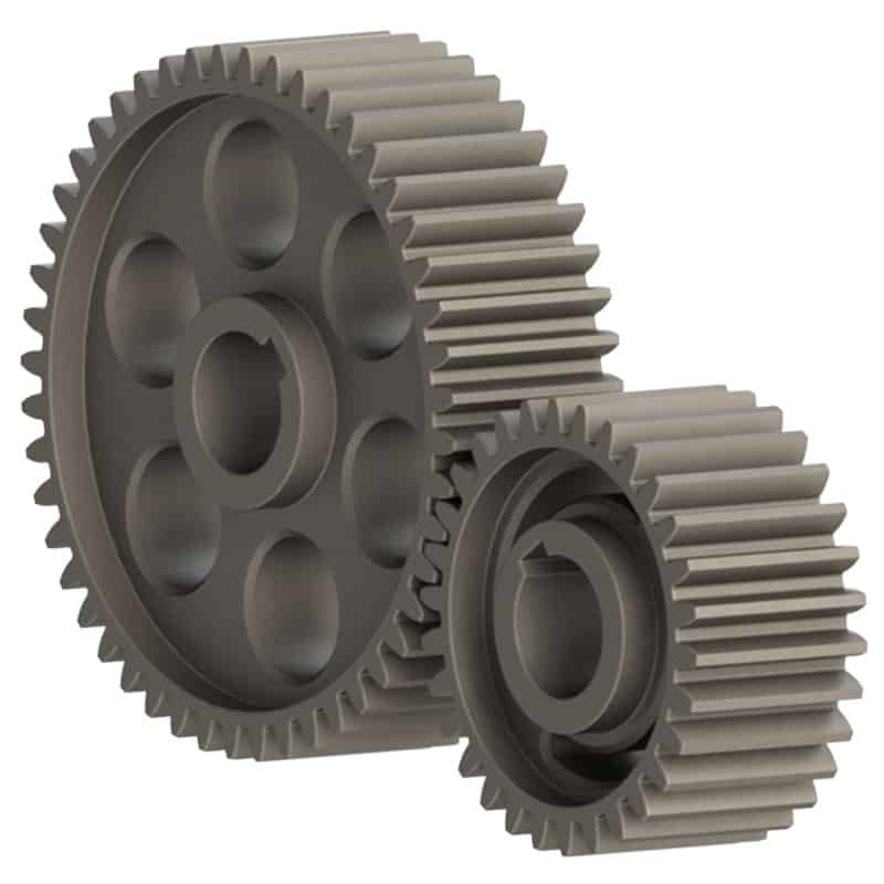
Precision Transmission Parts
|
Custom CNC Machining Parts Service |
|
|
Quotation |
According to your drawing(size, material,and required technology, etc) |
|
Materials |
Aluminum, Copper, Brass, Stainless Steel, Steel, Iron, Alloy, Titanium etc. |
|
Surface Treatment |
Anodizing, Brushing, Galvanized, laser engraving, Silk printing, polishing, Powder coating, etc. |
|
Tolerance |
+/- 0.005mm-0.01mm, 100% QC quality inspection before delivery, can provide quality inspection form |
|
Processing |
CNC Turning, Milling, Drilling, Hobbing, Polishing, Bushing, Surface Treatment etc. |
|
Drawing Formats |
Solid Works, Pro/Engineer, UG, AutoCAD(DXF, DWG), PDF, TIF etc. |
5-axis CNC Milling Parts
|
Material Available |
|||||
|
Aluminum |
Stainless Steel |
Brass |
Copper |
Iron |
Plastic |
|
AL6061 |
SS201 |
C35600 |
C11000 |
20# |
POM |
|
AL6063 |
SS301 |
C36000 |
C12000 |
45# |
Peek |
|
AL6082 |
SS303 |
C37700 |
C12200 |
Q235 |
PMMA |
|
AL7075 |
SS304 |
C37000 |
C15710 |
Q345B |
ABS |
|
AL2571 |
SS316 |
C37100 |
etc… |
Q345B |
Delrin |
|
AL5052 |
SS416 |
C28000 |
|
1214/1215 |
Nylon |
|
ALA380 |
etc… |
C26000 |
|
12L14 |
PVC |
|
etc… |
|
C24000 |
|
Carbon steel |
PP |
|
|
|
C22000 |
|
4140 / 4130 |
PC |
|
|
|
etc… |
|
etc… |
etc… |
|
Surface Treatment |
Material Available |
|
As machined |
All metals |
|
Smoothed |
All metals and Plastic (e.g aluminum, steel,nylon, ABS) |
|
Powder Coated |
All metals ( e.g aluminum, steel) |
|
Brushing |
All metals (e.g aluminum, steel) |
|
Anodized Hardcoat |
Aluminum and Titanium alloys |
|
Electropolished |
Metal and plastic (e.g aluminum, ABS) |
|
Bead Blasted |
Aluminum and Titanium alloys |
|
Anodized Clear or Color |
Aluminum and Titanium alloys |
Application Field
Company Profile
HangZhou CZPT Intelligent Technology Co. Ltd was established in 2003. Since established, we always focus on precision transmission and mechanical parts manufacturing & processing. We have a professional R&D team and advanced gear hobbing machine, gear grinding machine, gear shaping machine, CNC Lathe machines and milling machines, which can give comprehensive solutions according to user’s requirements, from the design.
we bulid us through help others succes. CZPT always focuses on the development ability, and now, it owns more than 30 patents. Our company has several advanced engineering design softwares and applied more than 20 new technologies and new processes. And also, it is certified by ISO 9001: 2015 and ISO 14001: 2015.
For more than 10 years, our company has been committed to the production and processing of precision parts and non-standard automation design. With a highly qualified workforce, relying on rich experience in precision processing and international leading equipment, the company has established strategic partnerships with world-renowned enterprises in the fields of aviation, medical and industrial precision test and measurement equipment.
FAQ
Q1: How to get a quotation?
A1: Please send us drawings in igs, dwg, step etc. together with detailed PDF.If you have any requirements, please note,
and we could provide professional advice for your reference.
Q2: How long can i get the sample?
A2: Depends on your specific items,within 7-10 days is required generally.
Q3: How to enjoy the OEM services?
A3: Usually, base on your design drawings or original samples, we give some technical proposals and a quotation to you, after your agreement, we produce for you.
Q4: Will my drawings be safe after sending to you?
A4: Yes, we will keep them well and not release to third party without your permission. Of course, we would ensure the safety of the drawing.
Q5: What shall we do if we do not have drawings?
A5: Please send your sample to our factory,then we can copy or provide you better solutions. Please send us pictures or drafts with dimensions(Length,Hight,Width), CAD or 3D file will be made for you if placed order.
| Application: | Motor, Electric Cars, Motorcycle, Machinery, Marine, Agricultural Machinery, Car, Industrial Machine |
|---|---|
| Hardness: | Hardened Tooth Surface |
| Gear Position: | External Gear |
| Manufacturing Method: | Rolling Gear |
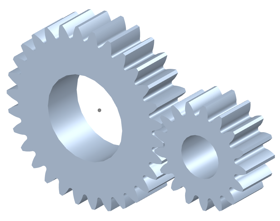
| Toothed Portion Shape: | Spur Gear |
| Material: | Stainless Steel |
| Samples: |
US$ 500/Piece
1 Piece(Min.Order) | |
|---|
| Customization: |
Available
| Customized Request |
|---|
How do you ensure proper alignment when connecting spur gears?
Proper alignment is crucial when connecting spur gears to ensure smooth and efficient gear operation. Here’s a detailed explanation of how to ensure proper alignment when connecting spur gears:
- Visual Inspection: Start by visually inspecting the gears, gear shafts, and associated components for any visible misalignment or damage. Look for signs of wear, uneven tooth engagement, or any abnormalities that may affect alignment.
- Shaft Alignment: Align the gear shafts accurately before connecting the gears. Proper shaft alignment ensures that the gears are positioned correctly relative to each other. This can be achieved through various alignment techniques, such as using alignment tools, laser alignment systems, or measuring devices. The goal is to ensure parallel or coaxial alignment between the gear shafts.
- Backlash Adjustment: Adjust the backlash between the gear teeth to achieve proper alignment. Backlash refers to the slight gap between the mating teeth of gears. It is important to maintain an appropriate amount of backlash to allow for smooth gear engagement and minimize the risk of binding or jamming. Follow the manufacturer’s recommendations or industry standards for the recommended backlash range and adjust as necessary during gear installation.
- Check Gear Mesh: Verify the gear meshing pattern to ensure proper alignment. The gear teeth should mesh smoothly and evenly without any signs of excessive or uneven contact. If there are indications of improper meshing, such as concentrated contact on a specific area of the tooth, it may imply misalignment or other issues that need to be addressed.
- Shim Adjustment: If misalignment is detected, shimming can be employed to correct it. Shimming involves placing thin metal shims between the gear and the shaft to adjust the positioning and alignment. Shims are available in various thicknesses, allowing for precise alignment adjustments. Careful measurement and selection of the appropriate shim thickness can help achieve the desired alignment.
- Tightening Bolts: When connecting the gears to the shafts, ensure that the bolts or fasteners are tightened evenly and to the recommended torque specifications. Uneven tightening can introduce misalignment or uneven load distribution, leading to gear misalignment and potential issues.
- Post-Installation Verification: After connecting the gears, perform a final verification of the alignment. Rotate the gears manually or through the gear system’s intended operation and observe the gear meshing behavior. Look for any signs of abnormal noise, vibration, or irregular tooth engagement. If any issues are detected, further adjustments or inspections may be necessary.
- Regular Maintenance: Implement a proactive maintenance program that includes periodic inspections and alignment verification. Gears can experience wear or misalignment over time due to factors such as load variations, temperature changes, or prolonged operation. Regular maintenance allows for early detection and correction of alignment issues, ensuring optimal gear performance and longevity.
Proper alignment is essential for maximizing the efficiency, durability, and reliability of spur gear systems. By following these alignment practices and considering the manufacturer’s recommendations, industry standards, and expert advice, you can ensure proper alignment when connecting spur gears.
It’s important to note that the specific alignment techniques and procedures may vary depending on the gear system’s design, size, application, and other factors. Consulting with gear manufacturers, engineers, or alignment specialists can provide further guidance on the recommended alignment practices for your specific gear system.
How do you install a spur gear system?
Installing a spur gear system involves several steps to ensure proper alignment, engagement, and operation. Here’s a detailed explanation of how to install a spur gear system:
- Preparation: Before installation, gather all the necessary components, including the spur gears, shafts, bearings, and any additional mounting hardware. Ensure that the gear system components are clean and free from debris or damage.
- Shaft Alignment: Proper shaft alignment is crucial for the smooth operation of a spur gear system. Ensure that the shafts on which the gears will be mounted are aligned accurately and parallel to each other. This can be achieved using alignment tools such as dial indicators or laser alignment systems. Adjust the shaft positions as needed to achieve the desired alignment.
- Positioning the Gears: Place the spur gears on the respective shafts in the desired configuration. Ensure that the gears are positioned securely and centered on the shafts. For shafts with keyways, align the gears with the key and ensure a proper fit. Use any necessary mounting hardware, such as set screws or retaining rings, to secure the gears in place.
- Checking Gear Engagement: Verify that the teeth of the gears mesh properly with each other. The gear teeth should align accurately and smoothly without any excessive gaps or interference. Rotate the gears by hand to ensure smooth and consistent meshing throughout their rotation. If any misalignment or interference is observed, adjust the gear positions or shaft alignment accordingly.
- Bearing Installation: If the spur gear system requires bearings to support the shafts, install the bearings onto the shafts. Ensure that the bearings are the correct size and type for the application. Press or slide the bearings onto the shafts until they are seated securely against any shoulder or bearing housing. Use appropriate methods and tools to prevent damage to the bearings during installation.
- Lubrication: Apply a suitable lubricant to the gear teeth and bearings to ensure smooth operation and reduce friction. Refer to the gear manufacturer’s recommendations for the appropriate lubrication type and amount. Proper lubrication helps minimize wear, noise, and heat generation in the gear system.
- Final Inspection: Once the gears, shafts, and bearings are installed, perform a final inspection of the entire spur gear system. Check for any unusual noises, misalignment, or binding during manual rotation. Verify that the gears are securely mounted, shafts are properly aligned, and all fasteners are tightened to the specified torque values.
It’s important to follow the specific installation instructions provided by the gear manufacturer to ensure proper installation and operation. Additionally, consult any applicable industry standards and guidelines for gear system installation.
By carefully following these installation steps, you can ensure a well-aligned and properly functioning spur gear system in your machinery or equipment.

Are there different sizes and configurations of spur gears available?
Yes, there are various sizes and configurations of spur gears available to suit different applications and requirements. Here’s a detailed explanation of the different options when it comes to sizes and configurations of spur gears:
Sizes: Spur gears come in a wide range of sizes to accommodate different torque and speed requirements. The size of a spur gear is typically specified by its pitch diameter, which is the diameter of the pitch circle. The pitch diameter determines the gear’s overall size and the spacing between the teeth. Spur gears can range from small gears used in precision instruments to large gears used in heavy machinery and industrial equipment.
Module: Module is a parameter used to specify the size and spacing of the teeth on a spur gear. It represents the ratio of the pitch diameter to the number of teeth. Different module sizes are available to accommodate various gear sizes and applications. Smaller module sizes are used for finer tooth profiles and higher precision, while larger module sizes are used for heavier loads and higher torque applications.
Number of Teeth: The number of teeth on a spur gear can vary depending on the specific application. Gears with a higher number of teeth provide smoother operation and distribute the load more evenly, whereas gears with fewer teeth are typically used for higher speeds and compact designs.
Pressure Angle: The pressure angle is an important parameter that determines the shape and engagement of the teeth. Common pressure angles for spur gears are 20 degrees and 14.5 degrees. The selection of the pressure angle depends on factors such as load capacity, efficiency, and specific design requirements.
Profile Shift: Profile shift is a design feature that allows modification of the tooth profile to optimize the gear’s performance. It involves shifting the tooth profile along the gear’s axis, which can affect factors such as backlash, contact ratio, and load distribution. Profile shift can be positive (when the tooth profile is shifted towards the center of the gear) or negative (when the tooth profile is shifted away from the center).
Hub Configuration: The hub refers to the central part of the gear where it is mounted onto a shaft. Spur gears can have different hub configurations depending on the specific application. Some gears have a simple cylindrical hub, while others may have keyways, set screws, or other features to ensure secure and precise mounting.
Material and Coatings: Spur gears are available in various materials to suit different operating conditions and requirements. Common materials include steel, cast iron, brass, and plastic. Additionally, gears can be coated or treated with surface treatments such as heat treatment or coatings to enhance their wear resistance, durability, and performance.
Mounting Orientation: Spur gears can be mounted in different orientations depending on the application and space constraints. They can be mounted parallel to each other on parallel shafts, or they can be mounted at right angles using additional components such as bevel gears or shafts with appropriate bearings.
In summary, there is a wide range of sizes and configurations available for spur gears, including different pitch diameters, module sizes, number of teeth, pressure angles, profile shifts, hub configurations, materials, coatings, and mounting orientations. The selection of the appropriate size and configuration depends on factors such as torque requirements, speed, load capacity, space constraints, and specific application needs.


editor by CX 2023-09-11